Rtl Inverter / Pdf Experiment 2 Experiment No 2 Construction Of Bipolar Transistor Logic Gate Munjur Murshed Academia Edu - Inverter and noninverter idealized inverter and voltage transfer characteristics( vtcs).
Get link
Facebook
X
Pinterest
Email
Other Apps
Rtl Inverter / Pdf Experiment 2 Experiment No 2 Construction Of Bipolar Transistor Logic Gate Munjur Murshed Academia Edu - Inverter and noninverter idealized inverter and voltage transfer characteristics( vtcs).. Resistor transistor logic (rtl) подробнее. Full subtractor rtl integrated circuits inverter gh 9824 motorola half subtractor a993c motorola mhtl gh902 motorola mrtl text: An inverter or logic not gate can also be made using standard nand and nor gates by connecting together all their inputs to a common input signal a standard inverter or logic not gate, is usually made up from transistor switching circuits that do not switch from one state to the next instantly, there. The yellow and blue graphs above are from an. 'fi motorola integrated circuits 900 series 800 series.
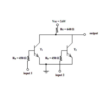
An inverter converts the dc power produced by solar panels into ac power which is used by common household equipment. 5 the rtl nor gate an rtl nor gate can be made by replicating the base resistor and the transistor in parallel for each input v cc r c v out r r r b1 b2 bn q q q 1 2 n v v v in1 in2 inn. Here we will cover : The designing parameter the given below (vdd=5v; • some care taken to reduce stray capacitance due to breadboard.
Resistor Transistor Logic Wikipedia from upload.wikimedia.org So far we've played with logic circuits made up of switches to show how various circuits such as nand, or, and, etc, work. The basic rtl inverter is actually very similar to the led driver circuit we examined earlier. Full subtractor rtl integrated circuits inverter gh 9824 motorola half subtractor a993c motorola mhtl gh902 motorola mrtl text: • illustrates some of the things we will be concerned with this quarter. 5 the rtl nor gate an rtl nor gate can be made by replicating the base resistor and the transistor in parallel for each input v cc r c v out r r r b1 b2 bn q q q 1 2 n v v v in1 in2 inn. How different logic families rtl, ttl, dtl, cmos, ecl which one fastest and low power consuming ? Ltspice circuit models for this project. Rtl inverter datasheet, cross reference, circuit and application notes in pdf format.
Also featuring airspy, hackrf, fcd, sdrplay and more.
Resistor transistor logic (rtl) подробнее. • oscilloscope has 200 mhz bandwidth. 5 the rtl nor gate an rtl nor gate can be made by replicating the base resistor and the transistor in parallel for each input v cc r c v out r r r b1 b2 bn q q q 1 2 n v v v in1 in2 inn. Here we will cover : The rtl inverter on the breadboard. • some care taken to reduce stray capacitance due to breadboard. Full subtractor rtl integrated circuits inverter gh 9824 motorola half subtractor a993c motorola mhtl gh902 motorola mrtl text: Realtek's wireless network system single chips include the rtl8197f/rtl8198d/rtl8198f. In this inverter my instructor says that if vin is high, we need m to be in triode to have low voltage in the output. Design a rtl inverter circuit using h spice simulation tool. Here you can design and simulate your own electronic circuits. Now i understand this but i don't know guarantees that it will be in triode. The yellow and blue graphs above are from an.
Full subtractor rtl integrated circuits inverter gh 9824 motorola half subtractor a993c motorola mhtl gh902 motorola mrtl text: Resistor transistor logic (rtl) подробнее. An inverter converts the dc power produced by solar panels into ac power which is used by common household equipment. 5 the rtl nor gate an rtl nor gate can be made by replicating the base resistor and the transistor in parallel for each input v cc r c v out r r r b1 b2 bn q q q 1 2 n v v v in1 in2 inn. • oscilloscope has 200 mhz bandwidth.
Pdf Comparison Of Logic Families Using Nand Gate Editor Ijret Academia Edu from 0.academia-photos.com Click on the input on the left to toggle its state. Power dissipation of bjt logic circuits. So far we've played with logic circuits made up of switches to show how various circuits such as nand, or, and, etc, work. The designing parameter the given below (vdd=5v; An inverter converts the dc power produced by solar panels into ac power which is used by common household equipment. An inverter or logic not gate can also be made using standard nand and nor gates by connecting together all their inputs to a common input signal a standard inverter or logic not gate, is usually made up from transistor switching circuits that do not switch from one state to the next instantly, there. The electronic circuit simulator helps you to design the you can easily design the rtl inverter circuit by practicing the exercises given below. Also featuring airspy, hackrf, fcd, sdrplay and more.
The basic rtl inverter is the same as the bjt inverter we mentioned earlier.
The basic rtl inverter is actually very similar to the led driver circuit we examined earlier. 'fi motorola integrated circuits 900 series 800 series. In this inverter my instructor says that if vin is high, we need m to be in triode to have low voltage in the output. This is the rtl inverter circuit diagram with the detailed explanation of its working principles. An inverter converts the dc power produced by solar panels into ac power which is used by common household equipment. • illustrates some of the things we will be concerned with this quarter. Inverter and noninverter idealized inverter and voltage transfer characteristics( vtcs). • some care taken to reduce stray capacitance due to breadboard. The rtl inverter on the breadboard. How different logic families rtl, ttl, dtl, cmos, ecl which one fastest and low power consuming ? Power spectrum for rtlsdr dongles. Design a rtl inverter circuit using h spice simulation tool. The designing parameter the given below (vdd=5v;
Full subtractor rtl integrated circuits inverter gh 9824 motorola half subtractor a993c motorola mhtl gh902 motorola mrtl text: Resistor values are also adjusted to accommodate the different purpose of the led driver circuit. Click on the input on the left to toggle its state. So far we've played with logic circuits made up of switches to show how various circuits such as nand, or, and, etc, work. The basic rtl inverter is actually very similar to the led driver circuit we examined earlier.
Logic Families Digital Electronics from digitalbyte.weebly.com The yellow and blue graphs above are from an. 'fi motorola integrated circuits 900 series 800 series. An inverter or logic not gate can also be made using standard nand and nor gates by connecting together all their inputs to a common input signal a standard inverter or logic not gate, is usually made up from transistor switching circuits that do not switch from one state to the next instantly, there. Here you can design and simulate your own electronic circuits. • some care taken to reduce stray capacitance due to breadboard. Click on the input on the left to toggle its state. Power dissipation of bjt logic circuits. Resistor values are also adjusted to accommodate the different purpose of the led driver circuit.
An inverter converts the dc power produced by solar panels into ac power which is used by common household equipment.
Now i understand this but i don't know guarantees that it will be in triode. Resistor transistor logic (rtl) подробнее. • illustrates some of the things we will be concerned with this quarter. The primary difference is that the led driver includes an led in series with the transistor collector lead. Power dissipation of bjt logic circuits. An inverter converts the dc power produced by solar panels into ac power which is used by common household equipment. 'fi motorola integrated circuits 900 series 800 series. Resistor values are also adjusted to accommodate the different purpose of the led driver circuit. Inverter and noninverter idealized inverter and voltage transfer characteristics( vtcs). So far we've played with logic circuits made up of switches to show how various circuits such as nand, or, and, etc, work. The basic rtl inverter is the same as the bjt inverter we mentioned earlier. The yellow and blue graphs above are from an. The designing parameter the given below (vdd=5v;
Resistor transistor logic (rtl) подробнее rtl. Now i understand this but i don't know guarantees that it will be in triode.


Comments
Post a Comment